










Box for formwork for universal conduit entries

recommendations

Central transition casing for universal conduit entries
Artikel-No. 9914.10
E-No 155006908
  • Material: Polyethylene
  • Processing temperature: -5 °C / + 60 °C

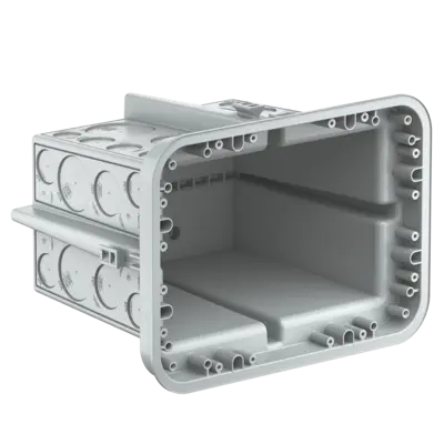
Box for formwork for universal conduit entries

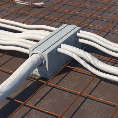
The new box for formwork for concrete structures is primarily used to bring together conduits of different diameters from electrical distribution boards and cable routes. The range of accessories includes plastic screw-down cover and moisture-proof cover made from anodised aluminium. Six metal screws are supplied with both types of cover. The metal screws for the moisture-proof cover are rust-proof. Where insulation material is retrofitted to the underside of a ceiling slab, extension elements can be used to bridge the distance between the concrete slab and the finished ceiling.The advantage of these frames is that they can be combined to accommodate insulation of any thickness. The plastic screw-down cover is designed for neat and secure attachment and for use in dry areas. The moisture-proof cover is suitable for wet rooms.
  • Front part can be nailed to the formwork before fitting of the conduits
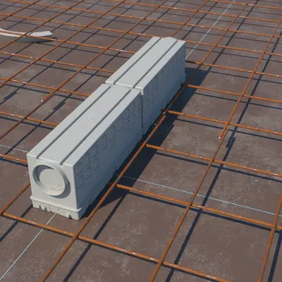
  • Can be connected in a row as often as required
  • Short nails, less deformation when hammering in
  • Upper part can be snapped onto front part
  • Pre-assembled nails are supplied
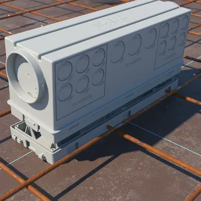
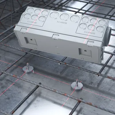
  • Large number of pre-marked conduit entries, two entries max. M63 on the front side
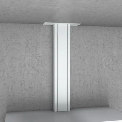
Application examples

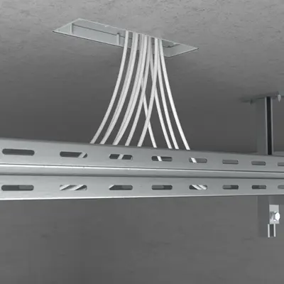
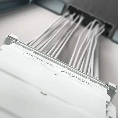
The flush-mounted formwork box for concrete structures is used to join together conduits of different sizes from electrical distribution boards...
...and cable routes.

Processing instructions

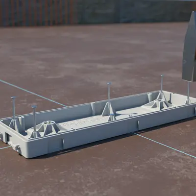
Secure the front part to the formwork using the six pre-installed nails.
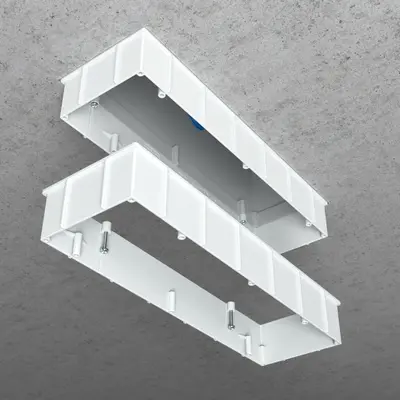
Click the box into place on the front part.
If necessary, several formwork boxes can be installed in a row, end to end, and the boxes can be connected to each other by opening the appropriate end entries (M40 to M63).
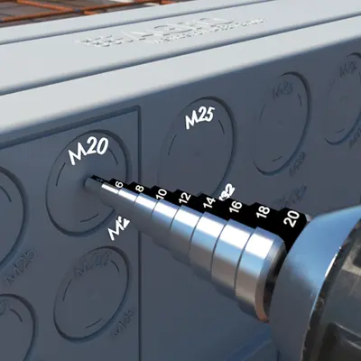
The required conduit entries can be opened using a step drill...
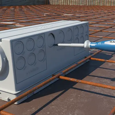
...or using a screwdriver and hammer.
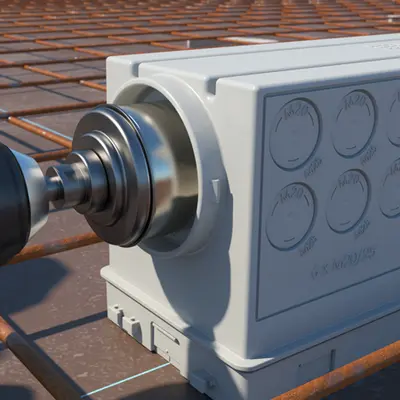
The end entries (M40 to M63) can be opened using a hole saw.
If numerous conduits of various sizes require insertion, four large openings can be created by removing their cover panels using a screwdriver and hammer.
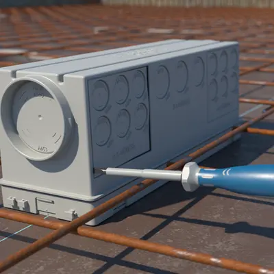
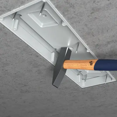
After the formwork has been removed, the box’s front panel can also be removed using a hammer and screwdriver as required.
Extension elements (Art.-No. 9914.10.68) can be used to pass through insulation material on the underside of a ceiling slab. Multiple elements can be stacked as required.
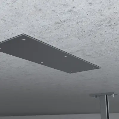
A neat finish can be achieved using a plastic screw-on cover (Art.-No. 9914.10.02, supplied with six screws)...
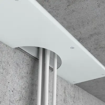
...or by using an aluminium water-resistant cover with anodised surface (Art.-No. 9914.10.03, supplied with six rustproof screws).

Application examples

Numerous entries for conduits from Ø 20 mm to Ø 63 mm.
The central transition casing for the exit of several conduits, e.g. is located in above in the lightweight wall...
...or surface-mounted electrical distribution...
...as well as cable routing systems.

Processing instructions

Fixing by means of steel nails.
Fixing by means of KAISER system magnet (Art. No. 1299-69) or KAISER system magnet PLUS (Art. No. 1299-70).
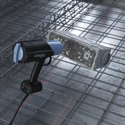
Fixing by means of hot glue.
If required, several central transition casings can be lined up next to each other.

Dimensions / Form

Product length:
330 mm
Product width:
120 mm
Product depth:
5 mm

Assembly / Installation

Assembly type:
BB (solid construction)

Safety / Properties

Special application:
on-site mixed concrete

Features

Number of screws:
6
Central transition casing for universal conduit entries
Artikel-No. 9914.10
E-No 155006908
  • Material: Polyethylene
  • Processing temperature: -5 °C / + 60 °C