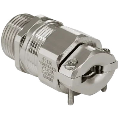








Professional cable glands for potentially explosive atmospheres

Explosion protection. Necessary more frequently than you might think.

n the 19th century, electrical technology made its way into both industry and the home. Immediately thereafter, the first fundamentals for protection against electrical explosions were developed because of the methane gas and coal dust which arose during the mining of anthracite coal. The advantages of electricity were so overwhelming that people started working intensively to come up with ways to prevent any possible meeting of explosive atmospheres and ignition sources – resulting from the use of electrical equipment – and in this way could avoid explosions.

This application in mining was just the start. The chemical and petrochemical industries as well as oil and gas extraction represent more application areas where explosion-proof equipment is needed. Additionally, organic chemistry, the paint and varnish industry as well as the pharmaceuticals industry all process and work with flammable liquids and gases. And today even more application areas are constantly emerging, for instance with the extraction and use of biogas or the ecological use of disposal sites and landfills. In the processing of wood and grain there are yet more potential sources of danger. The use of hydrogen is being discussed intensively, and here, too, this will lead to various applications requiring explosion protection.

Anyone who is involved professionally with industrial systems must now be very conscious about the topic of explosion protection. In many industries, gases, vapours or mists build up or escape during the manufacture, processing, transport or storage of combustible materials, and these are released into the environment. Combustible dust is created in other processes. When these are combined with oxygen in the air, a hazardous atmosphere can build up which if ignited results in an explosion.

Explosion protection is governed by the legislation of individual countries around the world. Differences in technical requirements specific to each country and the required permits for explosionproof equipment place high requirements on manufacturers, especially those with global operations, and these result in high costs for product development and approvals processes. In the wake of globalisation, though, it has been possible to make great strides towards uniform policies for explosion protection.
  • Directives and regulations

    Directive 2014/34 EC
    The new directives 2014/34/EC of the European Parliament and of the Council of 26 February 2014 on the harmonisation of the laws of the Member States adress manufacturers and users of equipment and protective systems for use in potentially explosive atmospheres. Since 20 April 2016 only products approved according to the new directions and with EC declaration of conformity can be brought to the market. The old certificates according to the former directives 94/9/EC remain valid. A recertification according to the directives 2014/34/EU is not necessary.

    IECEx
    The international IECEx scheme likewise serves for the conformity assessment and certification of equipment, systems and services for use in potentially explosive atmospheres. Introduced in 1996, the IECEx system supports the international harmonisation of standards and the issue of country- and regionneutral certificates of conformity (CoC) to simplify the free movement of goods around the world. There is already an extensive agreement between the European ATEX directives and the IECEx regulations as regards classes and requirements. This all means that ATEX could one day be replaced.

    In those countries which recognise IECEx, certified equipment, apparatus and systems can be put into service without additional tests. Today, IECEx is recognised not only in Europe but in many additional countries including Australia, New Zealand, Brazil, Canada, China, Japan, Korea, Malaysia, Singapore, South Africa, USA... You can find further information about the IECEx system and its rules as well as regulations, handbooks and procedures at www.iecex.com.

    “Equipment” refers to machines, apparatus, fixed or mobile devices, control components and instrumentation thereof and detection or prevention systems which, separately or jointly, are intended for the generation, transfer, storage, measurement, control and con- Version of energy for the processing of materials and which are capable of causing an explosion through their own potential sources of ignition.

    “Components” refers to any item essential for the safe functioning of equipment and protective systems but with no autonomous function.

    An “explosive atmosphere” is a mixture with air, under atmospheric condi-tions, of flammable substances in the form of gases, vapours, mists or dusts in which, after ignition has occurred, combustion spreads to the entire unburned mixture.

    A “potentially explosive atmosphere” is one which could become explosive due to local and operational conditions.

    The manufacturer must take great care to provide sufficient information and instructions necessary for the proper operation and maintenance of equipment.


    Prerequisites for certification
    In the annex of directives 2014/34 EC various modules for the commercialisation of equipment intended for use in potentially explosive atmospheres are defined. Modules III and IV are often used and applied at AGRO as well, and from them two certificates result:
    • EC type-examination certificate
    • Recognition of production quality assurance

    Both certificates are issued by accredited testing facilities after tests have been successfully completed.

    EC type-examination certificate
    The EC type-examination certificate is the document which is issued on the base of successfully passed technical testing according to the requirements of module B.

    Recognition of production quality assurance
    Module D demands tested and monitored production. It ensures that products placed on the market are identical with the test samples used for the EC type-examination certificate. The quality management system must be tested and certified according to EN/ISO/IEC 80079-34.

    CE declaration of conformity
    The CE declaration of conformity is based on the EC type-examination certificate and QS approval. With it, a manufacturer declares that it has observed all applicable standards, instructions and regulations. This is made visible with the CE symbol, which is a part of the marking.

    Standards
    Numerous standards which address explosion protection exist around the world. The scope of standards is, however, subject to continuous updates which reflect technical advances and increased societal requirements regarding safety. International harmonisation efforts around the world have as their goal globally unified safety standards to help break down trade barriers.
    Equipment is differentiated by the corresponding series of standards:
    • IEC / EN 60079 for electrical equipment (gases, vapours and dust)
    • EN 80079 for non-electrical equipment

    Which type of ignition protection a manufacturer selects depends on the type and intended function of the equipment. All standardised types of ignition protection within a given category are equivalent. A manufacturer confirms with the EC type-examination certificate, which belongs to the technical documentation, that its product conforms to ATEX directives.

    Certification
    Equipment intended for use in potentially explosive atmospheres may only be brought to market if they have undergone the conformity assessment procedures dictated in the directives. EC typeexamination certifications from a designated European testing facility are recognised within the entire EC.
  • The danger of explosion

    What protective measures can be taken to reduce the danger of explosion
    • avoid combustible substances
    • inerting (addition of nitrogen, carbon dioxide, etc.)
    • limiting concentration levels
    • improved ventilation
    • secondary explosion protection is necessary if the danger of explosion cannot be ruled out through primary explosion protection measures

    Equipment marking
    The following can be identified from the marking of electrical equipment for hazardous areas:
    • equipment manufacturer
    • a designation from which it can be identified
    • the area of use: underground I or other areas II
    • the categories which indicate if the device can be used in certain areas
    • the type(s) of ignition protection which the equipment fulfils
    • the overall identification of the certificate

    M this prefix stands for underground mines
    G this suffix stands for combustible gases, mists or vapours
    D this suffix stands for dust

    Numerals express the degree.

    Equipment category 1 very high degree of safety
    Equipment category 2
    high degree of safety
    Equipment category 3
    normal degree of safety

    Equipment protection level a very high degree of protection and thus a very high degree of safety
    Equipment protection level b high degree of protection and thus a high degree of safety
    Equipment protection level c normal degree of protection and thus an increased level of safety

    This results in the assignment of the equipment categories to the zones.

    Illustration 1: Filling station (gases and fumes)
    Illustration 2: Sack filling facility (dust)
Certificate
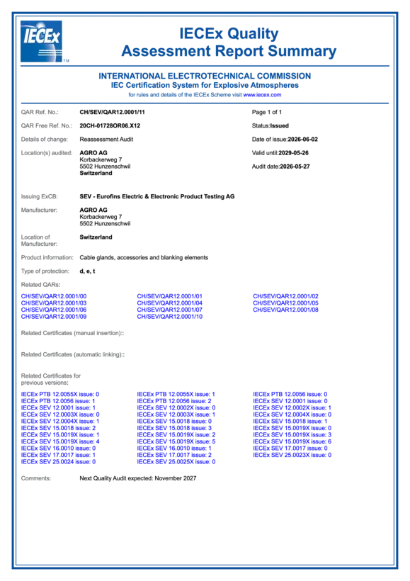
IECEx QUALITY ASSESSMENT REPORT SEV 12 ATEX 4107
491.1 KB | 01/09/2025
Ex cable glands.
Brochure
Ex cable glands.

Professional cable glands for potentially explosive atmospheres.

5 MB
  • Flameproof enclosures Ex d IIC (Serie 18)

    Certification including ageing and climatic tests
    Principle
    With ignition protection type Ex d IIC, components which can ignite an explosive atmosphere are arranged in a housing. This housing must contain the pressure of the explosion and an explosive mixture within itself, and it must prevent the explosion from spreading to the explosive atmosphere surrounding the housing.

    Important design parameters
    • The mechanical stability must correspond to that of a predetermined safety factor against internal explosion pressures.
    • Gaps between two parts of a housing must be designed sufficiently long and narrow that exiting hot gas cannot ignite an explosive atmosphere which might be present in the hazardous area.
    • The parameters for the gaps preventing an arc-through, width/length, are different for Explosion Subgroups IIA, IIB and IIC. The highest requirements on gap parameters are placed on the housings of Explosion Subgroup IIC.
    • Safety bracket to prevent loosening in case of vibration

    Applications
    Equipment which during normal operation can generate sparks or electric arcs and/or hot components; this includes switchgear and circuit breakers, controls, motors, transformers, slip rings, collectors, regulating resistors, fuses, lighting fixtures, heating cartridges and friction brakes. Cable glands for flameproof enclosures are tested according to IEC/EN 60079-1 for the following points:
    • mechanical design and pressure testing
    • electrical and thermal behaviour

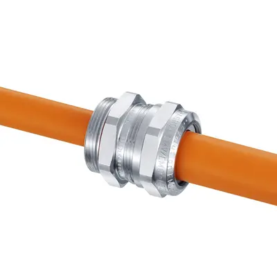
    1 Entry threads
    Long entry threads in metric, Pg, gas pipe or NPT designs provide maximum safety with respect to the quality of attachment.

    2 Spanner surfaces
    Large, solid spanner surfaces on the pressure nut and bottom section allow safe tightening with the assembly tool.

    3 Guaranteed sealing capability
    The ingenious sealing insert and matching inner contours ensure a targeted deformation of the insert and thus guarantee its tightness. Protection Class IP68 (30 bar) facilitate optimal usage.

    Testing standards
    IEC 60079-0:2011 / EN 60079-0:2012   
    IEC 60079-1:2007 / EN 60079-1:2007
    IEC 60079-31:2008 / EN 60079-31:2009
  • Flameproof enclosures Ex d IIC (Ex Compact)

    Certification including ageing and climatic tests
    Ex e II principle
    In the case of ignition protection with an increased safety type, operation is based on the equipment preventing ignition of the explosive atmosphere which can also leak into the housing. The equipment may not reach temperatures which are above the temperature class of gases which could potentially arise in the place of use, and sparks caused by electrical or mechanical means may also not occur. In electrical machines, electrical-thermal testing is thus of particular importance. In operation, protection against overloading is essentially important to maintaining explosion protection.

    Important design parameters
    • There are special protection requirements for non-insulated active components.
    • Air and creepage gaps are dimensioned larger than is generally the case in industry. Special requirements apply to the IP protection classes which must be maintained.
    • More stringent requirements apply to windings with mechanical stability and insulating capacity, and the windings must be protected against elevated temperatures.

    Applications
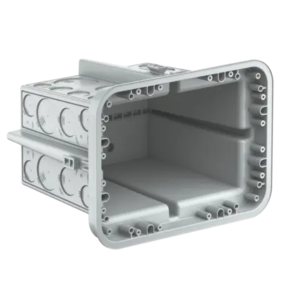
    Installation materials such as junction boxes and distribution boxes, terminal compartments for heaters, storage batteries, transformers, inductive ballasts, electrical motors, squirrel cage induction motors, lighting fixtures. Cable glands for increased safety are tested according to IEC/EN 60079-7 for the following points:
    • mechanical design
    • electrical-thermal testing

    1 Entry threads
    Long entry threads in metric designs allow maximum safety with respect to the quality of attachment.

    2 Compact design
    The compact design allows space-saving assembly on equipment, and the large clamping range reduces the number of different types.

    3 Guaranteed sealing capability
    The ingenious sealing insert and matching inner contours ensure a targeted deformation of the insert and thus guarantee its tightness. Protection Class IP68 (30 bar) facilitate optimal usage.

    Testing standards
    IEC 60079-0:2011 / EN 60079-0:2012
    IEC 60079-1:2007 / EN 60079-1:2007
    IEC 60079-7:2006 / EN 60079-7:2007
    IEC 60079-31:2008 / EN 60079-31:2009
  • Increased safety Ex e II (Progress and pressure balance element)

    Certification including ageing and climatic tests
    Principle
    In the case of ignition protection with an increased safety type, operation is based on the equipment preventing an ignition of the explosive atmosphere which can also leak into the housing. The equipment may not reach temperatures which are above the temperature class of gases which could potentially arise in the place of use, and sparks caused by electrical or mechanical means may also not occur. In electrical machines, electrical-thermal testing is thus of particular importance. In operation, protection against overloading is essentially important to maintaining explosion protection.

    Important design parameters
    • Special protection requirements for non-insulated active components.
    • Air and creepage gaps are dimensioned larger than is generally the case in industry. Special requirements apply to the IP protection classes which must be maintained.
    • More stringent requirements apply to windings with mechanical stability and insulating capacity, and the windings must be protected against elevated temperatures.

    Applications

    Installation materials such as junction boxes and distribution boxes, terminal compartments for heaters, storage batteries, transformers, inductive ballasts, electrical and squirrel cage induction motors, lighting fixtures. Cable glands for increased safety are tested according to IEC/EN 60079-7 for the following points:
    • mechanical design
    • electrical-thermal testing

    1 Short, long or special entry threads
    Progress® cable glands with short or long entry threads in metric or Pg designs can be used with existing threads or, in the case of drilled through holes, with locknuts.

    2 Visible safety
    The small bead on the sealing insert confirms the proper tightening torque.

    3 High distortion protection
    The integrated retaining grooves in the lower part and in the sealing insert ensure protection against twisting.

    4 Guaranteed sealing capability
    Inner contours matched to the sealing insert ensure a targeted deformation of the insert and thus guarantee its tightness. Protection Class IP68 to 10 bar as well as IP69K allow a wide range of uses.

    Certified according to
    IEC 60079-0:2011 (Ed. 6)  / EN 60079-0:2012 + A11:2013
    IEC 60079-7:2015 (Ed. 5) / EN 60079-7:2015
    IEC 60079-31:2013 (Ed. 2) / EN 60079-31:2014
  • Increased safety Ex e II (combination conduit glands)

    Certification including ageing and climatic tests
    Principle
    In the case of ignition protection with an increased safety type, operation is based on the equipment preventing an ignition of the explosive atmosphere which can also leak into the housing. The equipment may not reach temperatures which are above the temperature class of gases which could potentially arise in the place of use, and sparks caused by electrical or mechanical means may also not occur. In electrical machines, electrical-thermal testing is thus of particular importance. In operation, protection against overloading is essentially important to maintaining explosion protection.

    AGRO combination conduit glands provide an optimal mix if you want to feed cables inside a conduit into an enclosure and at the same time want a secure seal and strain relief for the cables.

    Attention!

    Only metallic or metal-braided conduits may be applied!

    Important design parameters
    • There are special protection requirements for non-insulated active compo-nents.
    • Air and creepage gaps are dimensioned larger than is generally the case in industry. Special requirements apply to the IP protection classes which must be maintained.
    • More stringent requirements apply to windings with mechanical stability and insulating capacity, and the windings must be protected against elevated temperatures.

    Applications
    For installations where cable protection is important such as metalworking ma-chines or where mechanical damage can occur or effects due to weather must be excluded. Conduit glands for increased safety are tested according to IEC/EN 60079-7 for the following points:
    • mechanical design
    • electrical-thermal testing

    1 Short entry threads, metric
    Progress® cable glands with short entry threads can be used with existing screw threads.

    2 Grounding
    The screened tap connection is accomplished with a brass contact sleeve instead of the gasket (3a) over 360°.

    3 Guaranteed sealing capability
    The sealing capability of the combination conduit gland is ensured not only between the conduit and the conduit gland (3a) but also through the sealing insert in the cable gland (3b) at the entrance into the housing.

    Certified according to
    IEC 60079-0:2011 (Ed. 6)  / EN 60079-0:2012 + A11:2013
    IEC 60079-7:2015 (Ed. 5) / EN 60079-7:2015
    IEC 60079-31:2013 (Ed. 2) EN 60079-31:2014
  • Increased safety Ex e II (synthetic cable glands Progress® GFK)

    Certification including ageing and climatic tests
    Principle
    In the case of ignition protection with an increased safety type, operation is based on the equipment preventing an ignition of the explosive atmosphere which can also leak into the housing. The equipment may not reach temperatures which are above the temperature class of gases which could potentially arise in the place of use, and sparks caused by electrical or mechanical means may also not occur. This applies not only to normal operation but also during predictable malfunctions. In electrical machines, electrical-thermal testing is thus of particular importance. In operation, protection against overloading is essentially important to maintaining explosion protection.

    Important design parameters
    • Special protection requirements for non-insulated active components.
    • Air and creepage gaps are dimensioned larger than is generally the case in industry. Special requirements apply to the IP protection classes which must be maintained.
    • More stringent requirements apply to windings with mechanical stability and insulating capacity, and the windings must be protected against elevated temperatures.

    Applications
    Installation materials such as junction boxes and distribution boxes, terminal com-partments for heaters, storage batteries, transformers, inductive ballasts, electrical motors, squirrel cage induction motors, lighting fixtures. Cable glands for increased safety are tested according to IEC/EN 60079-7 for the following points:
    • mechanical design
    • electrical-thermal testing

    1 Entry threads
    Progress® cable glands with entry threads in metric or Pg designs can be used with existing threads or, in the case of drilled through holes, with locknuts.

    2 High distortion protection
    The integrated retaining grooves in the lower part and in the sealing insert ensure protection against twisting.

    3 Guaranteed sealing capability
    Inner contours matched to the sealing insert ensure a targeted deformation of the insert and guarantee a perfect seal.

    Certified according to
    IEC 60079-0:2011 (Ed. 6) / EN 60079-0:2012 + A11:2013
    IEC 60079-7:2015 (Ed. 5) / EN 60079-7:2015
    IEC 60079-31:2013 (Ed. 2) / EN 60079-31:2014
  • Intrinsic safety Ex i II

    Certification including ageing and climatic tests
    Principle
    A type of ignition protection in which the equipment contains intrinsically safe electrical circuits. An electrical circuit is intrinsically safe when neither a spark nor a thermal effect can cause the ignition of a given explosive atmosphere. The conditions for undisturbed operation and certain error conditions are established in this standard. Different requirements apply for areas with combustible dust:
    • Additional housing in Protection Class IP 6X if dust deposits can become a problem.
    • The electrical circuit must be designed for at least Explosion Group IIB.

    Important design parameters
    • Selection of certain components for electrical and electronic circuits.
    • Reduction of the allowable loading of the components compared to normal industrial applications with regard to
      - voltage because of electrical stability
      - current with respect to heating
    • The voltage and current values, including a safety factor, are continually limited to such a low level that it is certain that excessive temperatures cannot arise, while sparks and electric arcs during interruptions or short circuits have so little energy that they are unable to ignite an explosive atmosphere.

    Applications
    Measurement, monitoring and information systems and equipment, sensors based on physical, chemical or mechanical principles and with limited power, and actuators based on optical, acoustic and to a limited extent also on mechanical principles. AGRO cable glands are tested for increased safety, and through the marking with the blue housing they may also be used within intrinsically safe areas i II according to IEC / EN 60079-11
    • mechanical design
    • electrical-thermal testing

    1 Entry threads

    Progress® cable glands with entry threads in metric or Pg designs can be used with existing threads or, in the case of drilled through holes, with locknuts.

    2 High distortion protection
    The integrated retaining grooves in the lower part and in the sealing insert ensure protection against twisting.

    3 Guaranteed sealing capability
    Inner contours matched to the sealing insert ensure a targeted deformation of the insert and guarantee a perfect seal.

    Certified according to
    IEC 60079-0:2011 (Ed. 6) / EN 60079-0:2012 + A11:2013
    IEC 60079-7:2015 (Ed. 5) / EN 60079-7:2015
    IEC 60079-31:2013 (Ed. 2) / EN 60079-31:2014

Accessories (expansions, reducers and closing screws)

Reduction fittings nickel-plated brass increased safety Ex e II
Artikel-No. EX3500.10.08
E-No 126340208
  • Outer thread metric
  • Inner thread metric
  • with O-ring
Enlarging fittings nickel-plated brass increased safety Ex e II
Artikel-No. EX3600.07.12
  • Outer thread Pg
  • Inner thread metric
  • with O-ring
Synthetic locking plugs for increased safety Ex e II
Artikel-No. 8841.12
E-No 126230300
  • Black RAL 9005
  • with O-ring
Synthetic locking pins for multi-duct cable glands
Artikel-No. 1310.020.07
  • Locking pins for cable glands

Contact a technical adviser

Do you have any questions about our products and services? We’re happy to help. Please enter your postcode below to find the right contact person for your enquiries. In addition to the contact persons at AGRO’s head office, your local contact persons will also be displayed.

Please select the appropriate business area:

Please enter your city or zip code:

Headline SEO-Summary, H2

Lorem ipsum dolor sit amet, consetetur sadipscing elitr, sed diam nonumy eirmod tempor invidunt ut labore et dolore magna aliquyam erat, sed diam voluptua.