






















Evolution EMC
EMC Series 85 Brass
EMC powerCONNECT
EMV Rapid Brass
EMC easyCONNECT Brass

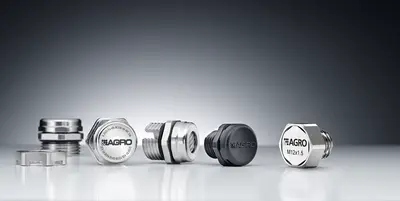
EMC cable glands

In an industrial setting, EMC is of particular importance, as complex machinery and plant are especially susceptible to electromagnetic interference. However, these undesirable EMC effects can be counteracted by effectively shielding all components. Good shielding reduces the interference emitted by operating resources whilst simultaneously reducing their susceptibility to electromagnetic interference.

However, it is not only the cables themselves but also the other installation components that must provide shielding. Cable glands, as passive components, must ensure that the quality of the shielding is maintained at the sensitive connection points and that no additional losses occur. In this respect, it is necessary not only to use an electric cable with maximum shielding, but also to employ EMC-compliant cable glands. Whilst there is no specific EMC standard for these components, they play a key role in ensuring that the manufacturers’ prescribed EMC requirements can be met.

With six different EMC-compliant cable glands, we offer customers the right product and the ideal connection option for every application. In the Progress® EMC easyCONNECT and easyCONNECT Multi Brass cable glands, the connection is made via an innovative spring clip. In the new Progress® EMC powerCONNECT, the advanced crimp sleeve guarantees a secure 360° shield contacting in the smallest of spaces

  • Guidelines and regulations

    But what exactly does EMC mean? Every electrical device generates an electromagnetic field around itself, which in turn can induce voltages and currents in other electrical devices. Depending on the intensity of this mutual interference, this can lead to malfunctions, reduced performance or even complete failure of the devices.

    The European standard EN 61000 defines the term EMC as follows: “Electromagnetic compatibility is the ability of electrical equipment to function satisfactorily in its electromagnetic environment without causing an unacceptable level of interference to that environment, which includes other equipment.” The active and passive components of this definition can be clearly illustrated using the example of a pacemaker: a pacemaker should not be affected at all by environmental influences, so as not to endanger the patient’s life. On the other hand, the patient must not suffer any harm solely as a result of the device’s operation.

    A basic distinction is made between electromagnetic interference in the low-frequency and high-frequency ranges. In the low-frequency range, interference arises from various forms of coupling (galvanic, inductive, capacitive) between two electrical circuits. At higher frequencies, from around 10 kHz upwards, interference is also caused by field-coupled interactions that affect the interference sink – that is, the receiver, an electrical device or an electrical installation. Furthermore, a distinction can be made between natural sources of interference, such as lightning, and artificial sources, such as radio transmitters, frequency converters and switching operations.

    With regard to EMC, it is not only technical but also legal aspects that are of interest. In general, electrical products, machinery and installations are subject to a wide range of directives, laws, regulations and rules. The legal provisions applicable at European level with regard to EMC are intended not only to ensure the free movement of goods within the single market but also to safeguard human health and safety, as well as environmental protection, radio spectrum protection and consumer protection. Consequently, only products that comply with the protection requirements set out in the EMC Directive (2014/30/EU) may be placed on the market within the EU. Accordingly, manufacturers must design their products in such a way that no unreasonable electromagnetic interference occurs between two devices or systems; this must be demonstrated through appropriate test procedures and is indicated by the CE mark.
Electromagnetic compatibility (EMC) with AGRO cable glands

  • Progress® EMC powerCONNECT

    TheProgress® EMC powerCONNECT, featuring the innovative, advanced crimp sleeve, guarantees secure 360° shield contacting. The direct transition from the braid to the base of the cable gland ensures remarkably low contact resistance. Thanks to its low design height, the screw attachment is ideal for use in the most confined spaces.

    1. Low contact resistance
      The direct contact between the braid and the cable gland cone results in extremely low contact resistance.

    2. Maximum leakage currents
      Consistently high contact pressure, achieved through the fixed crimp sleeve and the tightening of the intermediate piece to the stop, enables maximum leakage currents that are limited only by the shield cross-section.

    3. High flexibility
      High sealing performance combined withgreat flexibility. The two-part sealing inserts allow for a wide clamping range whilst maintaining the same protection rating (IP 68 / IP 69).

  • Progress® EMC easyCONNECT Brass

    TheProgress® EMV easyCONNECT cable gland ensures full control over the installation and compensates for tolerances in shield thickness to ensure a secure shield connection. The spring system enables good and secure shield contacting for both partially stripped shielded cables and fully exposed cable shields.

    1. Optimal shield contacting
      The powerful yet gentle clamping of the cable shield guarantees excellent shield contact and ensures extremely low transfer impedances. The special design of the contact spring not only provides a wide shield clamping range but also allows the cable gland to be dismantled without damaging the EMC braid.
  • Progress® EMC Rapid Brass

    The cable gland, featuring two connection options, enables very quick and easy shield contacting via an integrated contact plate. It ensures good contact with both partially stripped shielded cables and fully exposed cable shields, which can also be routed onwards.

    1. Low contact resistance
      The large-surface, flexible tongues of the contact plate maximise the contact area with the shield braid and allow for time-saving installation.

    2. Flexible contact options
      For a higher-quality 360° shield contacting, the contact plate can be ejected and the cut-to-size shield braid can be connected directly to the contact surface in the lower part of the cable gland via the contact sleeve.
  • Progress® EMC Brass

    Progress® EMC cable glands made of brass, featuring the tried-and-tested contact sleeve, enable 360° shield contacting when the shield braid terminates within the cable gland. The specific edge geometry of the contact sleeve prevents the shield braid from being sheared off.

    1. Minimal contact resistance
      The 360° concentric shield connection ensures minimal contact resistance.

    2. Constant contact pressure
      The interlocking combination of ‘sealing insert and contact sleeve’ guarantees constant contact pressure of the shield braid against the base.
  • Progress® EMC Series 85 Brass

    The patentedProgress® EMC Series 85 brass cable glands ensure a particularly low-impedance connection between the shielding braid and the metal housing, whilst also providing a secure cable entry.

    1. Optimal shield contacting
      The intermediate piece with its large flat surfaces enables flawless shield contacting with the shield braid across 360° via the force-amplifying collet segments. The copper strip ensures even force distribution across the shield braid.

    2. Highest leakage currents
      The solid collet ensures a concentric, low-impedance shield tap and can sustain leakage currents of up to 1.6 kA – and 3 kA for short periods.
  • EVolution EMC

    The patentedProgress® EMC Series 85 brass cable glands ensure a particularly low-impedance connection between the shielding braid and the metal housing, whilst also providing a secure cable entry.

    1. Optimal shield contacting
      The intermediate piece with its large flat surfaces enables flawless shield contacting with the shield braid across 360° via the force-amplifying collet segments. The copper strip ensures even force distribution across the shield braid.

    2. Highest leakage currents
      The solid collet ensures a concentric, low-impedance shield tap and can sustain leakage currents of up to 1.6 kA – and 3 kA for short periods.

Contact a technical adviser

Do you have any questions about our products and services? We’re happy to help. Please enter your postcode below to find the right contact person for your enquiries. In addition to the contact persons at AGRO’s head office, your local contact persons will also be displayed.

Please select the appropriate business area:

Please enter your city or zip code: