

















Professional cable entries for use in potentially explosive atmospheres.

Explosion protection. More often necessary than you might think.

In the 19th century, electrical engineering made its way into industry and households. Immediately afterwards, driven by the presence of methane and coal dust in coal mining, the first principles of electrical explosion protection were developed. The advantages of electricity were so compelling that intensive work was carried out to find ways and means of preventing the combination of explosive atmospheres and ignition sources – caused by the use of operating resources – and thus avoiding explosions.

The mining sector marked the beginning of its application. There is a particularly wide range of applications for explosion-protected operating resources in the chemical and petrochemical industries, as well as in the extraction of crude oil and natural gas. The organic chemistry sector, the paint and varnish industry and the pharmaceutical industry all handle and fit flammable liquids and gases. With the extraction and use of biogas, and the ecological utilisation of landfill sites, new areas of application are constantly emerging. Further potential sources of danger exist in the processing of wood and grain. The use of hydrogen is the subject of intense debate and is also leading to various applications in explosion protection in this field.

The subject of explosion protection should be at the forefront of the minds of all those who deal with industrial plants in a professional capacity. In many industries, gases, vapours or mists are generated or escape during the manufacture, processing, transport and storage of flammable substances, and are released into the surrounding environment. In other processes, flammable dusts are produced. When combined with the oxygen in the air, an explosive atmosphere can form, which, if ignited, will result in an explosion.

Worldwide, explosion protection is regulated by the laws of individual governments. Country-specific differences in technical requirements and the necessary approvals for explosion-protected devices pose significant challenges, particularly for manufacturers operating globally, and require considerable effort in terms of development and certification. In the course of globalisation, major progress has been made towards standardised guidelines for explosion protection.

  • Guidelines and regulations

    Directive 2014/34/EU
    The new Directive 2014/34/EU of the European Parliament and of the Council of 26 February 2014 on the harmonisation of legislation now forms the basis that is binding for manufacturers and users of devices or protective systems intended for use in potentially explosive atmospheres.

    Following a two-year transition period, from 20 April 2016 onwards, only products complying with the new directives and accompanied by the relevant EU declaration of conformity may be placed on the market. Certificates issued under Directive 94/9/EC remain valid. Recertification in accordance with the current Directive 2014/34/EU is not required.


    IECEx
    The international IECEx Scheme also serves to assess the conformity and certify devices, systems and services intended for use in potentially explosive atmospheres.

    Introduced in 1996, the IECEx system supports the harmonisation of standards worldwide and the issuance of country- and region-neutral certificates of conformity (CoC), thereby facilitating the free global movement of goods. There is already a high degree of alignment between the classes and requirements of the European ATEX Directives and the IECEx regulations. All of this means that ATEX could one day be superseded.

    In countries that recognise IECEx, certified operating resources, devices and installations can be put into service without additional testing. IECEx is now recognised not only in Europe but in many other countries, including Australia, New Zealand, Brazil, Canada, China, Japan, Korea, Malaysia, Singapore, South Africa and the USA... Further information on the IECEx system and its regulations, as well as guidelines, manuals and procedures, can be found at: www.iecex.com.

    The term ‘device’ refers to machinery, operating resources, fixed or mobile installations, control and component parts, as well as warning and prevention systems, which, individually or in combination, are intended for the generation, transmission, storage, measurement, regulation and conversion of energy and for the fitting of materials, and which have their own potential ignition sources and may therefore cause an explosion.

    ‘Components’ are defined as components that are necessary for the safe operation of devices and protective systems, but which do not themselves perform an autonomous function.

    An explosive atmosphere is defined as a mixture of air and flammable gases, vapours, mists or dusts in which, following ignition, a combustion process spreads to the entire unconsumed mixture.

    A potentially explosive area is an area in which the atmosphere may become explosive due to local and operational conditions.

    The manufacturer must provide sufficient information and instructions necessary for the professional installation, operation and maintenance of the device.


    Requirements for certification
    Directive 2014/34/EU defines various modules in its Annex for the placing on the market of devices intended for use in potentially explosive atmospheres. Modules III and IV are frequently used, resulting in two certificates:

    • The EU type-examination certificate
    • The Production Quality Assurance Approval

    Both certificates are issued by accredited testing bodies following the successful completion of tests and audits.


    EU Type Examination Certificate
    Module B governs the EU type examination. The EU type examination certificate is based on this. It is issued following successful technical product tests.

    Approval of Production Quality Assurance
    Module D requires tested and monitored production. It ensures that the products placed on the market conform to the test specimens specified in the EU Type Examination Certificate. An existing quality management system is assessed and certified in accordance with EN/ISO/IEC 80079-34.

    EU Declaration of Conformity
    The EU Declaration of Conformity is based on the EU Type Examination Certificate and the Production Quality Assurance Statement. Through this, the manufacturer declares compliance with the applicable standards, directives and regulations. This is indicated by the CE marking. Standards There are a large number of technical standards worldwide in the field of explosion protection. The standards landscape is subject to constant change due to adaptations to technical progress and higher societal demands on safety. International harmonisation efforts aim to establish uniform safety standards worldwide so that barriers to trade can be removed. Devices are categorised according to the relevant series of standards:

    • IEC / EN 60079 for electrical devices (gases, vapours and dusts)
    • EN 80079 for non-electrical devices

    The type of protection used by the manufacturer depends on the type and function of the device. All standardised types of protection within a category are equivalent. The manufacturer confirms in the EU type-examination certificate, which forms part of the technical documentation, that the product complies with the ATEX Directives.


    Certification
    Devices intended for use in potentially explosive atmospheres may only be placed on the market once they have undergone the conformity assessment procedure specified by the Directive. EU type-examination certificates issued by a notified European testing body are recognised throughout the EU.
  • Risk of explosion

    What protective measures can be taken to reduce the risk of an explosion?
    • Prevention of flammable
    • substances Inerting (addition of nitrogen, carbon dioxide, etc.)
    • Limiting concentrations
    • Improved ventilation
    • Secondary explosion protection is required if the risk of explosion cannot be ruled out by primary explosion protection measures.

    Equipment marking
    The labelling of electrical operating resources for explosion-protected areas must clearly indicate:

    • the manufacturer of the operating resources
    • a designation by which it can be identified
    • the area of use: underground (Zone I) or other areas (Zone II)
    • the categories indicating whether the device is suitable for use in specific zones,
    • the type(s) of ignition protection with which the operating resources comply,
    • the full identification of the certificate

    ‘M’ at the beginning stands for underground mines
    ‘G’ at the end stands for flammable gases, mists or vapours
    ‘D’ at the end indicates dust

    The digits indicate the degree of protection.

    Equipment category 1: very high level of safety
    Equipment category 2: high level of safety
    Equipment category 3: a normal level of safety

    Equipment protection level a: very high degree of protection and therefore a very high level of safety
    Equipment protection level b: high degree of protection and therefore a high level of safety
    Equipment protection level c: normal degree of protection and therefore an increased level of safety

    This determines the allocation of equipment categories to the zones.

    Figure 1: Petrol station (gases and vapours)
    Figure 2: Bag-filling station (dust)
  • Pressure-resistant enclosure Ex d IIC (Series 18)

    Certification including ageing and climatic testing
    Principle
    In the Ex d IIC type of protection, components that could ignite a potentially explosive atmosphere are housed within a housing. This housing must withstand the pressure of an explosion of a potentially explosive mixture inside it and prevent the explosion from propagating to the potentially explosive atmosphere surrounding the housing.

    Key design parameters

    • The mechanical strength must comply with a specified safety factor against internal explosion pressures.
    • Gaps between two enclosure parts must be designed to be sufficiently narrow and long to ensure that escaping hot gas cannot ignite a potentially explosive atmosphere that may be present in the potentially explosive area.
    • The parameters of the flame-proof gap – width and length – differ for explosion subgroups IIA, IIB and IIC. The most stringent requirements regarding gap parameters apply to housings in explosion subgroup IIC.
    • A retaining clip prevents loose fittings due to vibrations

    Applications
    Operating resources in which sparks or arcs and/or hot parts occur during normal operation, such as switch devices and control gear, control systems, motors, transformers, slip rings, collectors, variable resistors, fuses, luminaires, heating elements and friction brakes. Cable glands for flameproof enclosures are tested in accordance with IEC/EN 60079-1 for the following aspects

    • mechanical design and pressure testing
    • electrical and thermal behaviour


    1. Connection threads
      Long connection threads in metric, Pg, gas pipe or NPT versions ensure maximum reliability in terms of fastening quality

    2. Flat surfaces
      Large, sturdy flat surfaces on the pressure nut and the base allow secure tightening using the assembly tool.

    3. Guaranteed leak-tightness
      The ingenious sealing insert and optimised internal contours ensure targeted deformation of the sealing insert and guarantee a perfect sealing performance. The IP68 protection rating (30 bar) enables optimum use.

    Test standards
    IEC 60079-0:2011 / EN 60079-0:2012
    IEC 60079-1:2007 / EN 60079-1:2007
    IEC 60079-31:2008 / EN 60079-31:2009
  • Pressure-resistant enclosure Ex d IIC (Ex Compact)

    Certification including ageing and climatic testing
    Principle
    Ex e II In the case of the ‘increased safety’ type of protection, the principle of operation is based on preventing the operating resources from igniting a flammable atmosphere, which may also penetrate the housing. The operating resources must neither reach temperatures exceeding the temperature class of gases that may be present at the site of use, nor must they generate any electrical or mechanical sparks. For electrical machines, therefore, electro-thermal testing is of paramount importance. During operation, protection against overload is essential for maintaining explosion protection.

    Important design parameters
    • Special protection requirements apply to uninsulated, live parts
    • Clearances and creepage distances must be larger than those in the general industrial sector. Special requirements apply to the IP protection ratings to be maintained.
    • Higher requirements apply to windings in terms of mechanical strength and insulating capacity, and the windings must be protected against elevated temperatures.

    Applications
    Installation materials, such as junction casings and connection casings, terminal compartments for heating systems, storage batteries, transformers, inductive ballast devices, electric and short-circuit-rotor motors, and luminaires. Cable glands designed for increased safety are tested in accordance with IEC/EN 60079-7 for the following aspects:

    • mechanical design
    • electrical and thermal testing


    1. Connection threads
      Long connection threads in metric design ensure maximum safety in terms of the quality of the fastening

    2. Compact design
      The compact design enables space-saving installation on the device, and the wide clamping range reduces the number of variants required.

    3. Guaranteed seal
      The sophisticated sealing insert and optimised internal contours ensure targeted deformation of the sealing insert and guarantee a perfect sealing. The IP68 protection rating (30 bar) enables optimum use.

    Test standards
    IEC 60079-0:2011 / EN 60079-0:2012
    IEC 60079-1:2007 / EN 60079-1:2007
    IEC 60079-7:2006 / EN 60079-7:2007
    IEC 60079-31:2008 / EN 60079-31:2009
  • Enhanced safety Ex e II (Progress and pressure equalisation element)

    Certification including ageing and climatic testing
    Principle
    In the case of the ‘increased safety’ type of protection, the principle of operation is based on preventing the operating resources from igniting a flammable atmosphere, which may also penetrate the housing. The operating resources must neither reach temperatures exceeding the temperature class of gases that may be present at the site of use, nor must they generate any electrical or mechanical sparks. In the case of electrical machines, therefore, electro-thermal testing is of paramount importance. During operation, protection against overload is essential for maintaining explosion protection.

    Important design parameters
    • Special protection requirements apply to uninsulated, live parts
    • Clearances and creepage distances must be larger than those in the general industrial sector. Special requirements apply to the IP protection ratings to be maintained.
    • Higher requirements apply to windings in terms of mechanical strength and insulating properties, and the windings must be protected against elevated temperatures.


    Applications
    Installation materials, such as junction casings and connection casings, terminal compartments for heating systems, storage batteries, transformers, inductive ballast devices, electric motors and luminaires. Cable glands designed for enhanced safety are tested in accordance with IEC/EN 60079-7 for the following aspects:

    • mechanical design
    • electrical and thermal testing


    1. Short, long or special connection threads
      Progress® cable glands with short or long connection threads in metric or Pg versions can be used where a thread is already present or in through-holes with a lock nut.

    2. Visible safety
      The small bead on the sealing insert confirms that the correct tightening torque has been applied.

    3. High anti-twist protection
      The longitudinal ribbing integrated into the base ensures high anti-twist protection via the sealing insert.

    4. Guaranteed seal
      Internal contours tailored to the sealing insert ensure targeted deformation of the insert, thereby guaranteeing a perfect sealing performance. The IP 68 protection rating up to 10 bar enables a wide range of applications.

    Certification in accordance with
    IEC 60079-0:2011 (Ed. 6) / EN 60079-0:2012 + A11:2013
    IEC 60079-7:2015 (Ed. 5) / EN 60079-7:2015
    IEC 60079-31:2013 (Ed. 2) / EN 60079-31:2014
  • Enhanced safety Ex e II (combination hose coupling)

    Certification including ageing and climatic testing
    Principle
    In the case of the ‘increased safety’ type of protection, the principle of operation is based on preventing the operating resources from igniting a flammable atmosphere, which may also penetrate the housing. The operating resources must not reach temperatures exceeding the temperature class of gases that may be present at the site of use, nor must any electrically or mechanically generated sparks occur. In the case of electrical machinery, therefore, electro-thermal testing is of paramount importance. During operation, protection against overload is essential for maintaining explosion protection.

    AGRO combination hose fittings are the ideal solution if you wish to feed cables through a protective conduit into a housing whilst ensuring secure sealing and strain relief for the cable.

    Warning!
    Only metallic or metal-braided protective conduits may be used!

    Important design parameters

    • Special protection requirements apply to uninsulated, live parts
    • Clearances and creepage distances must be larger than those in general industrial applications. Specific requirements apply to the IP protection ratings to be maintained.
    • Higher requirements apply to windings in terms of mechanical strength and insulating capacity, and the windings must be protected against elevated temperatures.

    Applications
    For installations where cable protection is important, e.g. metalworking machines, or where mechanical damage or weathering must be prevented. Hose fittings for enhanced safety are tested in accordance with IEC/EN 60079-7 for the following aspects:

    • mechanical design
    • electrical and thermal testing

    1. Short connection threads
      metric Progress® cable glands with short connection threads can be used where existing threads are present.

    2. Earthing
      The shield is connected via a brass contact sleeve instead of the sealing ring (3a) over 360°.

    3. Guaranteed leak-tightness
      The leak-tightness of the combination hose gland is ensured both between the hose and the hose gland (3a) and by the sealing insert in the cable gland (3b) when inserted into the housing.

    Certification in accordance with
    IEC 60079-0:2011 (Ed. 6) / EN 60079-0:2012 + A11:2013
    IEC 60079-7:2015 (Ed. 5) / EN 60079-7:2015
    IEC 60079-31:2013 (Ed. 2) EN 60079-31:2014
  • Enhanced safety Ex e II (Progress Kunstroff GFK)

    Certification including ageing and climatic testing
    Principle
    In the case of the ‘increased safety’ type of protection, the principle of operation is based on preventing the operating resources from igniting a flammable atmosphere, which may also penetrate the housing. The operating resources must neither reach temperatures exceeding the temperature class of gases that may be present at the site of use, nor must they generate any electrical or mechanical sparks. This applies both during normal operation and in the event of foreseeable faults. In the case of electrical machines, therefore, electro-thermal testing is of paramount importance. During operation, protection against overload is essential for maintaining explosion protection.

    Important design parameters
    • Special protection requirements apply to uninsulated, live parts
    • Clearances and creepage distances must be larger than those in the general industrial sector. Special requirements apply to the IP protection ratings that must be maintained.
    • Higher requirements apply to windings in terms of mechanical strength and insulation performance, and the windings must be protected against elevated temperatures.

    Applications
    Installation materials, such as junction casings and connection casings, terminal compartments for heating systems, storage batteries, transformers, inductive ballast devices, electric motors and luminaires. Cable glands designed for enhanced safety are tested in accordance with EC/EN 60079-7 for the following aspects:

    • mechanical design
    • electrical and thermal testing


    1. Connection thread
      Progress® cable glands with connection threads in metric or Pg versions can be used where a thread is already present or in through-holes with a lock nut.

    2. High anti-twist protection
      The longitudinal ribbing integrated into the base ensures a high level of protection against rotation via the sealing insert.


    3. Guaranteed Sealing
      Internal contours tailored to the sealing insert ensure targeted deformation of the insert and guarantee a perfect sealing performance.

    Certification in accordance with
    IEC 60079-0:2011 (Ed. 6) / EN 60079-0:2012 + A11:2013
    IEC 60079-7:2015 (Ed. 5) / EN 60079-7:2015
    IEC 60079-31:2013 (Ed. 2) / EN 60079-31:2014
  • Intrinsic safety Ex i II

    Certification including ageing and climatic testing
    Principle
    A type of ignition protection in which the operating resources contain intrinsically safe electrical circuits. An electrical circuit is intrinsically safe if neither a spark nor a thermal effect can cause ignition of a specific explosive atmosphere. The conditions for undisturbed operation and certain fault conditions are specified in this standard. Different requirements apply to areas containing combustible dust:

    • An additional housing with protection rating IP 6X if deposited dust could become a problem
    • The electrical circuit must be designed to meet at least Explosion Group IIB

    Key design parameters
    Selection of specific components for electrical and electronic circuits Reduction of the permissible load on components compared with standard industrial applications, in terms of

    • voltage, due to electrical strength
    • current, in terms of heating

    The voltage and current values, including a safety factor, are constantly limited to such a low level that impermissible temperatures certainly do not occur and that sparks and arcs in the event of an open circuit or short circuit have such low energy that they are insufficient to ignite an explosive atmosphere.

    Applications
    Measurement, monitoring and information systems and devices; sensors – based on physical, chemical or mechanical principles – and, with limited power, also actuators – based on optical, acoustic and, to a limited extent, mechanical principles. AGRO cable glands tested to the ‘increased safety’ standard are identifiable by their blue pressure nut and may also be used in the intrinsic safety zone II in accordance with IEC / EN 60079-11.

    • Mechanical design
    • Electrical-thermal testing

    1. Connection thread
      Progress® cable glands with connection threads in metric or Pg versions can be used where a thread is already present or, in the case of a through-hole, with a lock nut.

    2. High anti-twist protection
      The longitudinal ribbing integrated into the base ensures high anti-twist protection via the sealing insert.

    3. Guaranteed sealing
      Internal contours tailored to the sealing insert ensure targeted deformation of the insert and guarantee a perfect sealing result.

    Certification in accordance with
    IEC 60079-0:2011 (Ed. 6) / EN 60079-0:2012 + A11:2013
    IEC 60079-7:2015 (Ed. 5) / EN 60079-7:2015
    IEC 60079-31:2013 (Ed. 2) / EN 60079-31:2014

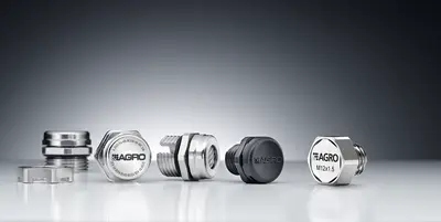
Accessories (expansions, reducers and closing screws)

Reduction fittings nickel-plated brass increased safety Ex e II
Artikel-No. EX3500.10.08
  • Outer thread metric
  • Inner thread metric
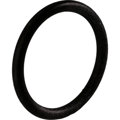
  • with O-ring
Enlarging fittings nickel-plated brass increased safety Ex e II
Artikel-No. EX3600.07.12
  • Outer thread Pg
  • Inner thread metric
  • with O-ring
Synthetic locking plugs for increased safety Ex e II
Artikel-No. 8841.12
  • Black RAL 9005
  • with O-ring
Synthetic locking pins for multi-duct cable glands
Artikel-No. 1310.020.07
  • Locking pins for cable glands

Contact a technical adviser

Do you have any questions about our products and services? We’re happy to help. Please enter your postcode below to find the right contact person for your enquiries. In addition to the contact persons at AGRO’s head office, your local contact persons will also be displayed.

Please select the appropriate business area:

Please enter your city or zip code: